66-70 B Body Frame Jig
(Note that this writeup is to help others build their own jig - we don't build/sell these)
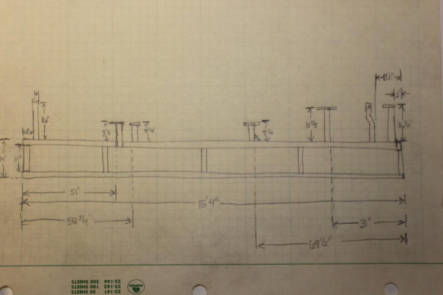
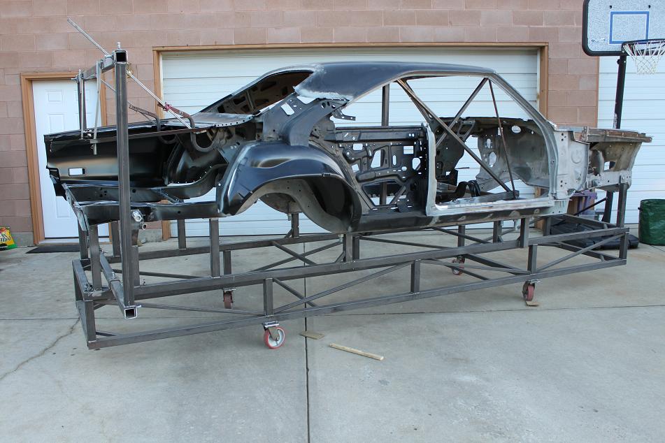
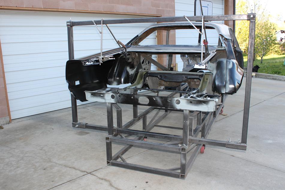
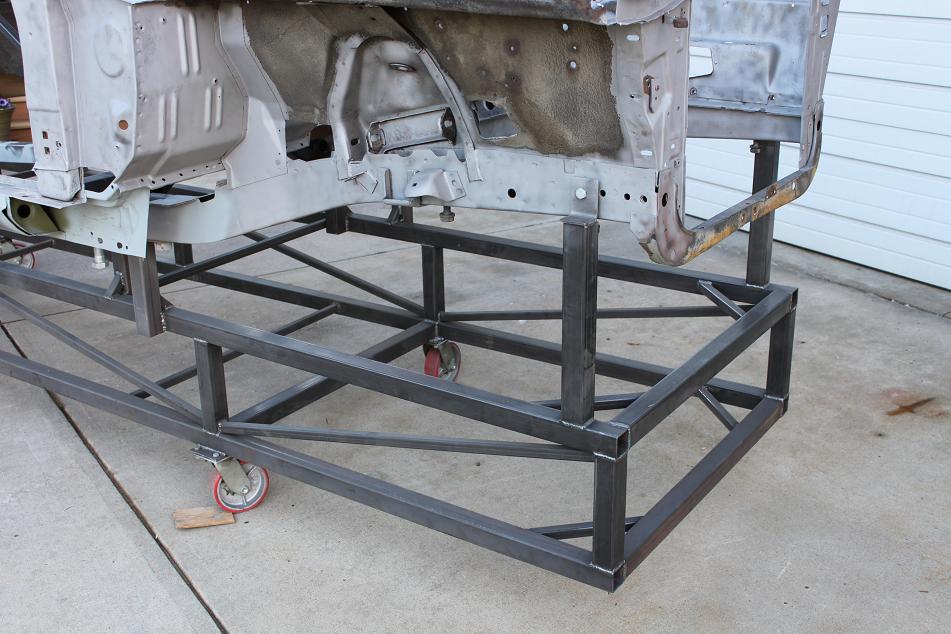
Here's some info on the 66-70 B Body frame jig. It's constructed of 1/8" wall 2" box. The long sections are 15' 4" long and the base is not a perfect rectangle but built to follow the front and rear frame rails from front to back. Center to center measurements of the box in the rear are 35 1/2". At the front, the center to center width of the tubing is 38 1/2". The smaller bracing is all 1/8" wall 1" box. The vertical box sections separating the two horizontal rings are 10" long giving the base of the jig a 14" height.
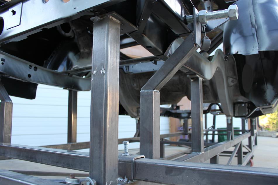
Alignment pegs and pads: Alignment pegs are built into the pads using 1" bolts and nuts. The nuts are welded below the support pads to align with the 1" frame alignment holes in the body. You can either run a threaded portion of a bolt up through the nut from the bottom and into the body or for a tighter fit, you can cut off the head of a bolt and run it in from the topside before putting the car on the jig. With it setup that way, the 1" doweled portion of the bolt fits tight in the body. The jig was built underneath the car using that type of setup. In the end, there's too much variance to use that tight of a setup from one car to the next. Also, the reproduction frame and torsion bar mount pieces will not have the holes in the exact same places anyway, so you'll be relying more on where the support pads hold everything and trying to get the critical parts (suspension mounts) back in the same place.
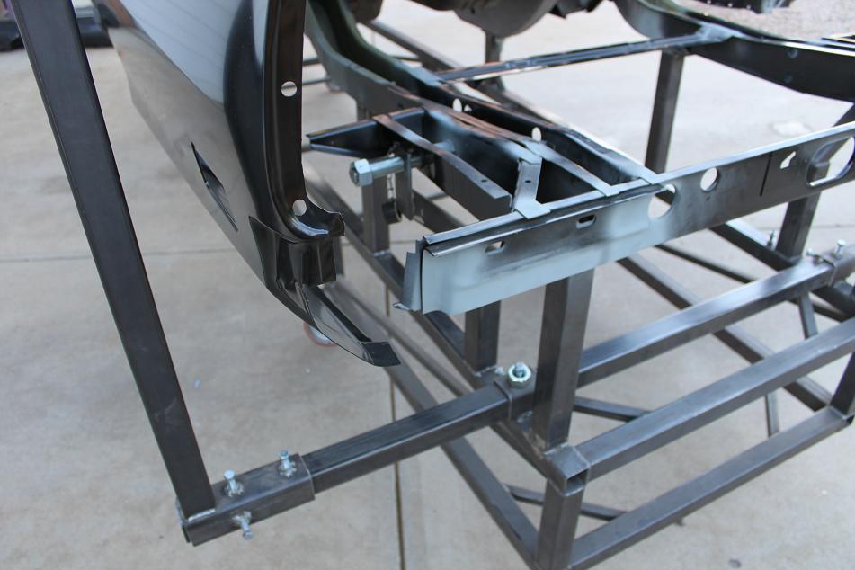
Leaf springs mounts: The jig also has a pegged setup to locate the rear leaf spring mounts. The front mounts are not permanently located on the jig, but a temporary setup was welded to the jig to locate the front perches when those needed replaced.
Support loop: The loop around the back of the car was wide enough to still allow replacing the quarter panels. Its overall width is 7'. The overall height of that loop is 53". It's all built with set screws thru 2 1/2" box (3/16" wall) used as sleeves for the 2" box (1/8" wall) to be able to disassemble it. The intent was to be able to weld multiple 2 1/2" box sleeves on the base to be able to install this loop in various places along the length of the car for vertical support.
Construction: 1/8" wall tubing moves a lot when welding. Don't run full beads on any bracing or things will move a lot when it cools. Trying to maintain a multi-point "pinned" setup while building the jig was very difficult. The mounting pads (and many other parts) had to be cut loose and rewelded many times as the base was being built. Once the main rings were built, the rest was built while shimmed and leveled underneath the car body which was leveled on a lift. When sections were added to the jig, the car was lowered and touching the pads and resting over the pegs. Between adding parts to the jig, the car was raised and then more often than not, something had to be cut loose in order to be able to drop the car back down on the pins.
The center to center measurement of the front to back tubing measures 35 1/2" in the back.
The vertical stubs seperating the two rings are 10" long.
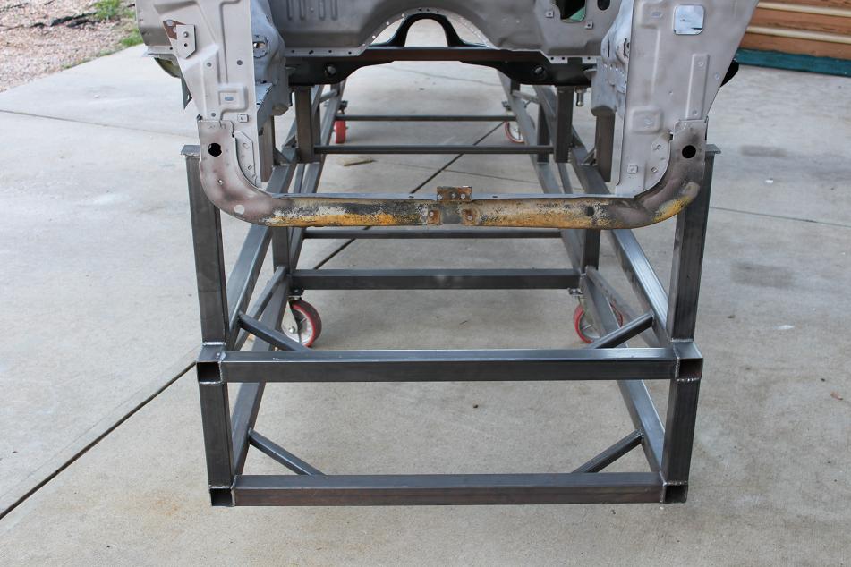
The center to center measurement of the front to back tubing measures 38 1/2" in the front.
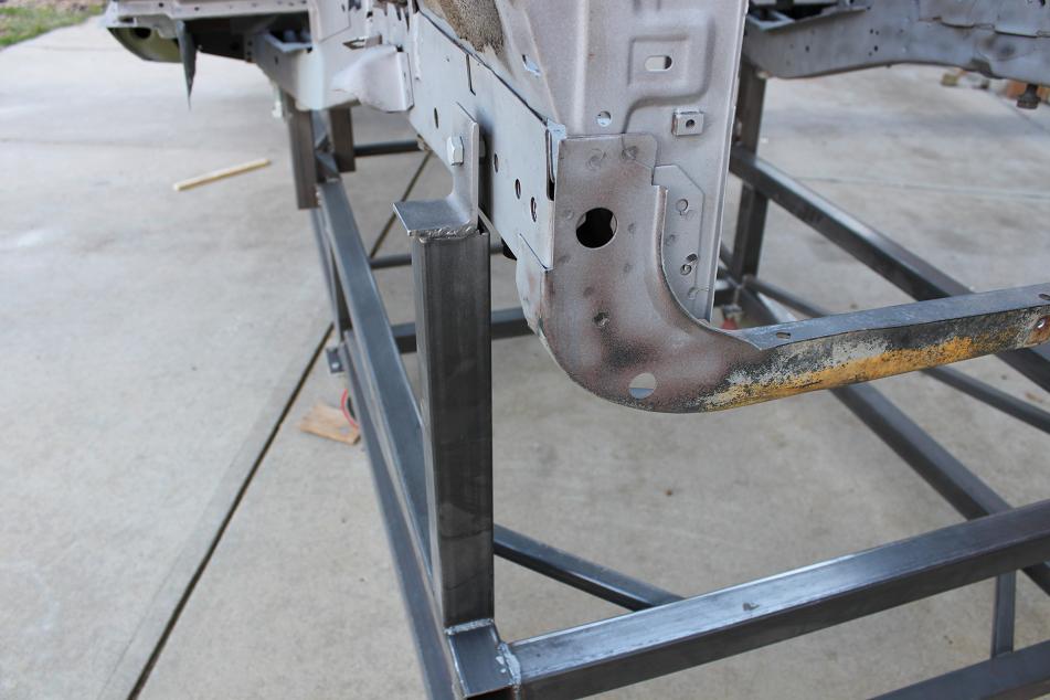
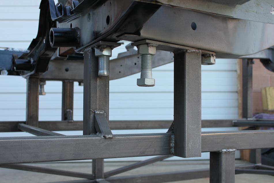
This picture shows the "pegged" version of the alignment bolt that's been flipped over since I couldn't use it after replacing the torsion bar crossmember as the alignment hole in the replacement part wasn't in the exact same place.
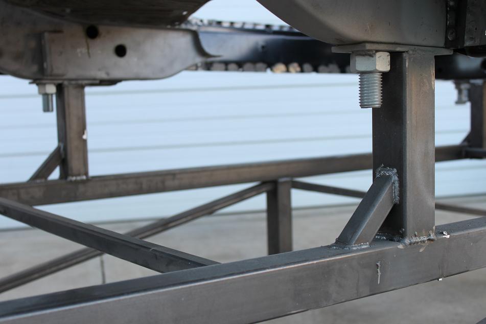
Here the bolts running up thru the nuts are pinned into the frame alignment holes.